Página 1 de 1

RTC for DIVIDE

Publicado: 23 Mar 2014, 23:43
por VELESOFT
Imagen
Imagen
Imagen

Eagle data: http://velesoft.speccy.cz/other/rtc_module_v01_full.rar

Firmware for GAL22V10: http://velesoft.speccy.cz/other/rtc_module_v01_full_GAL22V10D.zip (not tested)

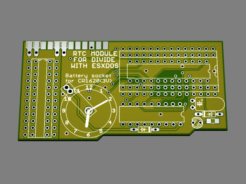
RTC module is small divide upgrade with RTC chip. System ESXDOS support it.

Module is designed specially for original DIVIDE interface and DIVIDE 57d2 or 57d3. (DIVMMC not contain signal WR on sockets, then is impossible make this module aslo for DIVMMC)

Your DIVIDE must have M-GAL and EEPROM chips in sockets.

Components:
GAL22V10
RTC72421A
battery CR1620 in socket
socket 24pins (thin)
socket 28pins (wide)
socket 18pins
some pinheads, capacitors, resistors

Installation to DIVIDE:
1) remove MGAL and EEPROM chips from sockets on your DIVIDE interface
2) insert RTC module to sockets
3) insert original MGAL and EEPROM chips to new sockets on RTC module board.

ESXDOS need file with RTC driver (author of ESXDOS can release).
After reboot will ESXDOS save files with true time.
For setup time exist utility (for setup RTC on MB02+ interface)

Re: RTC for DIVIDE

Publicado: 24 Mar 2014, 00:12
por mcleod_ideafix
Awesome!
Question: what those pads at the top of the PCB are for?

Re: RTC for DIVIDE

Publicado: 24 Mar 2014, 00:43
por VELESOFT
mcleod_ideafix escribió:Awesome!
Question: what those pads at the top of the PCB are for?


This mini bus conain pins for possibility connect kempston joystick interface (in future). Kempston joy interface will based only on joystick connector + resistor net + 74LS245 (very small PCB). GAL chip on RTC module make one signal "/JOYOE" and only this signal is connect to "minibus". Othen pins are not connect and will used for solder pins (for stability of joystick PCB)

Re: RTC for DIVIDE

Publicado: 30 Mar 2014, 18:45
por VELESOFT
final version of RTC module contain kempston joystick connector on board:
http://oldcomp.cz/viewtopic.php?f=39&t=1219&start=15#p13409

Re: RTC for DIVIDE

Publicado: 15 May 2015, 18:59
por mcleod_ideafix
VELESOFT: I'd like to implement this RTC chip inside the ZX-Uno. Although it wouldn't actually keep any date/time with the device powered off, it could be used from ESXDOS 0.8.6 and we could figure out a way to quickly update the clock.
Anyway, I'm watching your equations file, and I'd like to be sure about some things:

First: which I/O address is actually used to read/write to the RTC module? The equations show that the I/O address changes depending upon the position of two jumpers:
1100xxxx11101111 ( $CxEF ) if no jumpers are closed
0111xxxx00111011 ( $7x3B ) if jumper JP3 is closed
xxxxxxxx00000011 ($xx03 ) if jumper JP4 is closed

Second: which parts (bits) of the control registers are actually used? Does ESXDOS use any of these?
IRQ FLAG
STOP
30-seconds ADJ
HOLD
IRPT/STND
MASK
STOP
RESET

Third: is a .date or .time ESXDOS command available (or any other utility) so I can test whether the RTC is working properly?

Thanks!